Monday, July 18, 2016

7.4 - Research Assignment: Sense and Avoid Sensor Selection

An effective sense-and-avoid system will need multiple sensors able to detect manned and unmanned aircraft equipped with transponders broadcasting their position and those who aren't equipped or who refuse to broadcast their position.

A number of sense-and-avoid systems for UAS contain four primary types of sensors: Traffic Alert & Collision Avoidance system, better known as T-CAS, Automatic Dependent Surveillance-Broadcast, known as ADS-B, electro-optical sensors and radar.

T-CAS is a suite of airborne sensors designed to provide collision avoidance protection to aircraft. The system provides traffic advisories and recommends escape maneuvers (FAA, 2011). ADS-B is a precise satellite based system using GPS to define an aircraft's location and airspeed. The system then transmits this information to a network of ground stations. The ground stations in turn transmit the data to air traffic control as well as nearby aircraft equipped to receive the data via ADS-B (FAA, 2016). Electro optical cameras are sensors which detect light across a large spectrum and effectively enable the platform to 'see' (Keller, 2013).

The U.S. military recognized as early as 2001, the necessity for sense and avoid capabilities for its UAV program. The military employ a series of algorithms to collect and interpolate the data into a 'picture' for situational awareness for the pilot and the computer. While the Air Force has been researching airborne sense and avoid systems the Army has been researching ground based systems. The idea is to eventually tie both systems together to enable a UAS to fly anywhere (Insinna, 2014).

One such sense and avoid system under development is a project within DARPA's Fast, Lightweight, Autonomy (FAST) program. "DARPA’s FLA program aims to develop and test algorithms that could reduce the amount of processing power, communications, and human intervention needed for unmanned aerial vehicles (UAVs) to accomplish low-level tasks, such as navigation around obstacles in a cluttered environment" (DARPA, 2016).

There are micro UAVs capable of flying fast with significant agility but they are too small to contain the current sense and avoid technology. There are also extremely large military UAVs loaded with sensor suites able to provide a significant sense and avoid system. DARPA is attempting to find a middle ground which would provide key sense and avoid capabilities for smaller UAVs. 

DARPA's FAST quad copter was designed to autonomously navigate through a crowded indoor environment. The system is designed to be small enough to enter through a window and operate in a GPS deprived environment. One advancement DARPA succeeded in demonstrating was the use of sensors to navigate corridors, stairs and obstacles while using significantly less processing power. The quad copter demonstrated its ability to recognize or sense obstacles and fly around them.

The quad copter was also equipped with LIDAR, Sonar, inertial measurement sensors and several cameras. The platform is designed to operate autonomously which includes planning, sensing, perception and flight control. The next phase calls for more sophisticated algorithms allowing the quad copter to recognize or see obstacles from a greater distance and successfully navigate them at greater speeds. The plan also calls for more agility demonstrated via tight turns and sudden moves at high speeds.

DARPA's plan, once the sense and avoid system is operational for UAS, is to export the technology for use on UGS and UMS.

For this project, DARPA used a DJI Flamewheel 450 airframe, E600 motors with 12" propellers and 3DR Pixhawk autopilot.

The DJI Framewheel 450 has the following specifications:

Frame weight:  282 g
Diagonal Length:  450 mm
Price:  from as low as $32 (GetFPV, 2016)

The E600 motor with 12" propellers has the following specifications:

Recommended load:  600 g/axis
Maximum thrust:  1600 g/axis
Voltage:  14.8 V - 25.2 V
Weight:  90 g
Price:  Not available in my region (DJI, 2016)

The 3DR Pixhawk autopilot has the following specifications:

3 microprocessors
4 sensors
10 interfaces
Power system
Software (Newegg, 2016)

A FLA quadcopter self-navigates around boxes during initial flight data collection using only onboard sensors/software. DARPA’s FLA program aims to develop and test algorithms that could reduce the amount of processing power, communications, and human intervention needed for unmanned aerial vehicles (UAVs) to accomplish low-level tasks, such as navigation around obstacles in a cluttered environment

References:

DJI Store. (2016). Retrieved from https://store.DJI.com/product/E600-6

DARPA, FLA Program Takes Flight. (2016, February 12). Retrieved from http://www.darpa.mil/news-events/2016-02-12

FAA, Automatic Dependent Surveillance Broadcast (ADS-B) (2016, June 30). Retrieved from http://www.faa.gov/nextgen/programs/adsb/

FAA, Introduction to TCAS II, Version 7.1. (2011, February 28). Retrieved from http://www.faa.gov/documentLibrary/media/Advisory_Circular/TCAS%20II%20V7.1%20Intro%20booklet.pdf

GetPFV.com. (2016). Retrieved from
http://www.getfpv.com/dji-flamewheel-f450-basic-kit.html?utm_source=google_shopping&m=simple&gdffi=747627bc7e464db68e5f529d971aacf3&gdfms=62AA982B9F454C1190FB68274ECB5D47&gclid=CLexhbvF_s0CFVRahgodThYB4g

Insinna, V. (2014, May). National Defense. Military, Industry Racing to Create Sense-and-Avoid Systems. Retrieved from http://www.nationaldefensemagazine.org/archive/2014/may/pages/military,industryracingtocreatesense-and-avoidsystems.aspx

Keller, J. (2013, October 8). Electro-optical sensor payloads for small UAVs. Retrieved from http://www.militaryaerospace.com/articles/print/volume-24/issue-10/technology-focus/electro-optical-sensor-payloads-for-small-uavs.html


Newegg. Pixhawk flight Controller board 3d Robotics 32 Bit Autopilot System good for FL. (2016). Retrieved from http://www.newegg.com/Product/Product.aspx?Item=9SIA7BF34S0056&nm_mc=KNC-GoogleMKP-PC&cm_mmc=KNC-GoogleMKP-PC-_-pla-_-3D+Printers+Accessories-_-9SIA7BF34S0056&gclid=CKOjjp_D_s0CFcxahgodf9YB8g&gclsrc=aw.ds

Monday, July 11, 2016

6.4 Research Assignment - Control Station Analysis

Greensea Systems Inc is a company known for developing equipment specifically for unmanned underwater vehicles. One of the pieces of equipment developed by Greensea is a sophisticated command and control system designed for remote operated vehicles (ROVs). This system is known as Balefire. This is an off the shelf product designed to enable ROVs enhanced functionality.

Greensea develops software packages specifically for navigation and command and control of ROVs and AUVs. Greensea utilizes customized software as well as commercial software to ensure a user friendly, but powerful control system.


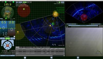
This photo provides a view of how the navigation, control, automation, sonar, and video data can be displayed in an easily discernible format.

Balfire provides the operator with key abilities to control and monitor the ROV. The Balefire basic system provides auto depth, auto altitude, heading, fly-by-wire and cruise control.  Enhancements normally incorporate “autopilots, station keeping, dynamic positioning, autonomous control modes, path following, mission planning and sensor fusion to the basic ROV system.” (Haun, 2014) Balefire’s control station presents these and additional features in a clear and concise manner designed for ease of operation.

Additional Control Modes Include
• Attitude Control: Roll, pitch, and heading
• Vertical Control: Depth and altitude
• Velocity Control: X/Y/Z velocities, Yaw rate
• Waypoints, routes, pre-planned missions
• Target tracking: Sonar and camera integration

Greensea’s system is modular in structure and designed to fit into a large number of ROV core inertial navigation system (INS), bringing more extensive command and control to the system. Greensea’s graphical user interface technology adds 2D navigation, chart plotting, payload management, mission planning, diagnostics and overall system control. The design makes this scalable and customizable to a large number of unmanned maritime systems. The system can interface with over 500 sensors and actuators. The system is also easily upgradable by downloading the program modules onto your computer.

The ease of operation of the Balefire system saves time and money on training and real world operations. The system has proven highly effective in increasing the operator’s efficiency and consistency.  

I was unable to identify any issues or challenges faced by current users or recommend changes to improve the system. There are over 300 current systems operating. The modular approach with the ease of software updates, the flexible hardware interface and the pleasing visual display makes this a highly sought after control and navigation system.

The Balefire system data depiction and presentation strategy is dependent on the selected modules. The module displays are presented in simple, straightforward formats. I have selected four examples of the dozen plus potential sensor suites below. As one can see, the presentation design and strategy is user friendly. The system is designed to improve the relationship between the operator and the ROV and the ROV and other computers and/or systems.


This photo demonstrates the navigation interface display for the ROV.


Image result for Greensea Control Systems for ROVs

This photo demonstrates the monitoring of some of the ROV electronics.


This photo depicts the intelligence valve pack.


References:

Greensea Control Systems for ROVs. Google Images. (2016). Retrieved from https://www.google.com/search?tbm=isch&tbs=rimg%3ACVYqnDrZ9rcvIjibUGAs6ZqIrS7QratbpBgVF0rM74v8OLyuWZnGgY0DdVqbUjTc0otkHWfVxNeNyCaHDh0qrCW46CoSCZtQYCzpmoitEVTUwK8V4lzsKhIJLtCtq1ukGBURVNTArxXiXOwqEgkXSszvi_1w4vBHikUbuwQ-qoyoSCa5ZmcaBjQN1EVz-9l4Y53r-KhIJWptSNNzSi2QRH8w8n_1-ZZ8cqEgkdZ9XE143IJhEH5xD-D2f15yoSCYcOHSqsJbjoEZGg0gXvf1U1&q=Greensea%20Control%20Systems%20for%20ROVs&ved=0ahUKEwjDt4Xej-fNAhWKTCYKHeosAQsQ9C8ICQ&dpr=1&biw=1536&bih=763#imgrc=EMifY41mZwhkxM%3A

Haun, E. (2014, July 14). Greensea Upgrades SeaView's ROV. Retrieved from http://www.marinelink.com/news/greensea-upgrades372905.aspx


Marine Technology. Greensea News. (2013, May 30). Retrieved from http://www.marinetechnologynews.com/news/c/greensea

Monday, June 27, 2016

4.5 - Research Assignment: Unmanned System Data Protocol and Format


General Dynamics Bluefin Robotics designs and sells five models within their highly sophisticated autonomous underwater vehicle (AUV) series known as Bluefin. The most recent addition to this series is the Bluefin 21, pictured below: 


https://blogger.googleusercontent.com/img/b/R29vZ2xl/AVvXsEjoIQ9OnlQzX9MHv8vpjBbgmbf0iFOBkOpyXmD1yfB6bBpN7_Q5jUuJsfSJ-rwUWnv5giI-90ENPDJTycEqfvuCcHLD1bbOPHTg1MESTewqAO3jRpoTHX2JT38o4Zw4qLTLLeRfj1NLcAMG/s1600/uuv2.png


The vast majority of AUVs and Remotely Operated Underwater Vehicles (ROVs) are designed with a single exterior shell. The Bluefin 21 is designed to house the propulsion system, payload and battery modules in separate sections, allowing for ease of payload and battery transitions while out at sea. This provides the ability for the AUV to be reconfigured and placed back into service very rapidly.  


The Bluefin 21 operates on a Graphic User Interface based tool suite. This software package interfaces between the Bluefin 21 and the operator. It enables the operator to plan the mission, monitor the AUV during parts of the mission, manage the data collected by the AUV and the payload sensors (if they are being stored in the tool suite), as well as conduct a post mission review. The internal data for the system is stored on a 4 gigabyte flash drive. 


The Bluefin 21 has over 70 sensor payloads engineered into the design. The most common exteroceptive sensor suite on the 21 is an "EdgeTech 2200-M 120/410 kHz side scan sonar, an EdgeTech DW-216 sub-bottom profiler and a Reson 7125 400 kHz multibeam echo sounder" (General Dynamics, 2016). The data can be collected and stored on board via a solid state drive. This can be uploaded while on the surface via an RF, Iridium or acoustic antenna; or can be transferred via an Ethernet cable (General Dynamics, 2016). 


The Edge Tech 2200 side scan sonar and the DW-126 sub-bottom profiler can either use the AUV's power supply, from which they draw very little, or can contain their own power source. The side scan sonar can be placed within the pressure hull or attached externally. The system is designed so the side scan sonar and sub-bottom profiler can operate in coordination with each other or independently. 


"The 200 kHz Reson 7125 multibeam echo sounder requires 48V DC 58W (Provided by sonar processor)  110/220 VAC 50/60Hz, 300W and takes up minimal space - Receive Array:  102 x 496 x 131 mm; Transmit Array:  100 x 259 x 117 mm; Link Control Unit:  530.9 x 174 mm; and the 7-P Processor:  431 x 146 mm."  (Reson Seabat, n.d.)  
 

Bluefin Robotics has an established system in place to ensure the sensor suites are integrated into the overall AUV strategy from the outset. The design of the AUV's "payload hardware interface" allows for a virtual plug and play for payloads from vendors who commonly work with Bluefin Robotics to newly designed payload/sensor systems from first time vendors. The engineers from various disciplines within Bluefin Robotics review and analyze the sensor suites to ensure system compatibility and ease of operation. This also includes data processing considerations. The Bluefin 21's power and communications center allows for interaction with new suites without requiring extensive redesign.  


This innovative design enables the use of the Bluefin 21 for a myriad of applications to include: Search and Salvage, Oceanography; Exploration; Mine Countermeasures and Unexploded Ordinance Detection (General Dynamics, 2016). 


References: 


Bluefin-21 Autonomous Underwater Vehicle (AUV), United States of America. (2016). Retrieved from http://www.naval-technology.com/projects/bluefin-21-autonomous-underwater-vehicle-auv/ 


General Dynamics Mission Systems (2016).  Bluefin Robotics, Bluefin-21. Retrieved from http://www.bluefinrobotics.com/vehicles-batteries-and-services/bluefin-21  


General Dynamics Mission Systems (2016).  Bluefin Robotics, Bluefin-21. Retrieved from http://www.bluefinrobotics.com/assets/Uploads/Maritime-Bluefin-21-UUV-01-0416.pdf 


General Dynamics Mission Systems (2016).  Bluefin Robotics, Bluefin-21. Retrieved from http://www.bluefinrobotics.com/technology/sensor-integration/ 


RESON SEABAT 7125 HIGH RESOLUTION MULTIBEAM ECHOSOUNDER. (n.d.) Retrieved from 
www.oceanscan.net/RESONSEABAT7125MULTIBEAMECHOSOUNDER%20(1).pdf